


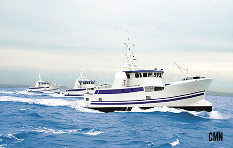
FABRICANT PROPULSION NAVALE POUR UNITES JUSQU’A 90 METRES
Spécialiste propulsion, fabrication hélices et lignes arbres porte-hélices complètes
Consultant
PROPULSION NAVALE PAR HELICES
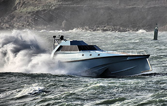
Plus qu’un fabricant et réparateur de systèmes de propulsion marine, FRANCE HELICES vous conseille dès les premiers plans de votre navire monocoque et multicoque pour la fabrication d’hélices, lignes d’arbres porte hélices complètes et drives de surface SDS.
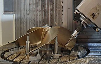
FABRICATION
PROPULSION NAVALE PAR HELICES
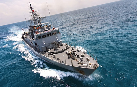
FRANCE HELICES développe, calcule, et fabrique des ensembles complets de propulsion pour votre bateau (ligne d’arbre porte hélice, hélice, chaise, gouvernail safran…) et systèmes de drives de surface SDS en France selon votre votre cahier des charges.
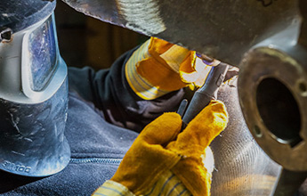
REPARATION
PROPULSION NAVALE PAR HELICES
Après un diagnostic en nos ateliers, FRANCE HELICES favorise quand cela est possible la réparation et la modification de votre propulsion.
Si votre hélice n’est pas réparable, FRANCE HELICES calcule votre hélice selon vos éléments techniques.
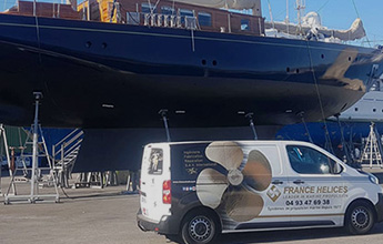
SAV
FRANCE ET INTERNATIONAL
Afin de garantir des performances optimales dans le temps, nous vous conseillons de faire contrôler votre matériel.
Notre coeur de métier est la recherche, le développement, la fabrication, la réparation et l’usinage de systèmes de propulsion marine par hélices sur-mesure haut de gamme. Notre mission est d’apporter des solutions techniques à notre clientèle. Nos sites de fabrication FRANCE HELICES assurent l’ensemble des fabrications hélices et usinages lignes d’arbres complètes avec un service qualité présents à tous les stades de la production.
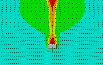
La propulsion doit être parfaitement adaptée aux caractéristiques du navire. Nous réalisons une étude technique suivant les exigences du client afin de calculer et concevoir une propulsion sur mesure (fabrication hélice et ligne arbre complète), idéale pour assurer une performance optimale (vitesse et accélération), des nuisances sonores réduites, un minimum de vibration, une économie d’énergie tout en maitrisant les phénomènes de cavitation.
votre propulsion MARINE sur-mesure

septembre 6, 2019
Euromaritime 2022

janvier 14, 2020
Dimdex

janvier 14, 2020
Navexpo

janvier 14, 2020
Navalia

janvier 14, 2020
Seawork

septembre 6, 2019
Cannes Yachting Festival 2022

septembre 6, 2019
mets / amsterdam
[insta-gallery id= »1″]